Encoder registration: the same registry, Android's own implementation
One encoder is registered per codec type, each marked as hardware. Codec selection, the candidate chain and the rule about switching lanes only before the first frame were covered in the article on the recording chain; this article only looks inside this implementation.
When it is created, the platform MIME string is chosen by codec, then the encoder is created by type. The configuration section sets these items: width and height, bitrate, frame rate, keyframe interval, profile, and disabling B-frames. The bitrate is not supplied by hand — when the upper layer does not set it, one is computed from resolution, frame rate and a few coefficients, then clamped.
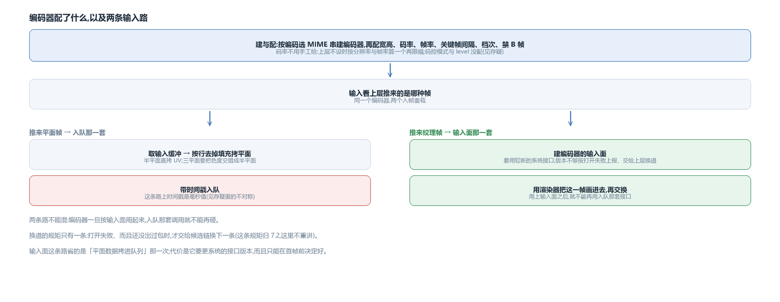
One thing is not configured: the rate control mode. No key such as constant bitrate or a quality tier is set; the bitrate is an average target. The other is that only the profile is set, not the level.
Two input paths, depending on which kind of frame the upper layer pushes
This implementation has two frame-input overloads, corresponding to two kinds of frames:
When a planar frame is pushed in, it goes through the queueing path: take an input buffer, strip the padding row by row and copy the planes — for the semi-planar variant the UV plane is copied directly, for the three-plane variant the two chroma planes have to be interleaved into a semi-planar one — then queue it with its timestamp.
When a texture frame is pushed in, it goes through the input-surface path: first create the encoder's input surface, then use its own EGL renderer to draw this frame into it, then swap. Once this path is used, the queueing interface can no longer be used.
The input surface requires a newer system API; when the version is too low, it is reported directly as an open failure and left to the upper layer to switch to the next candidate.
The step where it is drawn in
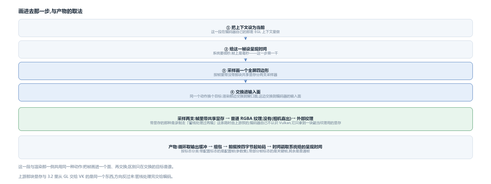
Each time, the renderer does three things: make the context current, set a presentation time for this frame (the system wants microseconds, while the timestamp on the frame is in milliseconds, so this step multiplies by one thousand), then sample and draw a full-screen quad, and finally swap into the input surface.
Sampling splits into two branches depending on whether the frame carries that shared graphics memory:
When recording takes the “process in the pipeline, then encode” path, the frame carries the graphics memory handed out by the pipeline, and sampling uses an ordinary RGBA texture; a camera-direct frame does not have this memory, so sampling uses an external texture, the same approach as the render side.
That is, this segment in front of the encoder shares the same action as the render side: draw the frame into a surface, then swap. The only difference is the swap target — on the render side it is the window surface, here it is the encoder's input surface.
The graphics memory in the frame: the output surface handed out by the upstream pipeline
The encoder itself knows nothing about Vulkan. The graphics memory in the frame is put there by upstream: during recording, if the output is not a CPU frame, the pipeline hands out its output surface, and what the frame object carries is that shared buffer (the same thing the render side hands from GL to VK, only in the opposite direction). The encode side only gets the fact of “a piece of graphics memory usable as a texture”.
The bitrate formula: pixel count times frame rate times two coefficients, then clamped
When the upper layer does not set a bitrate, this implementation computes one from resolution and frame rate: pixel count times frame rate, then times two coefficients — one is a content complexity factor, the other the encoder's own factor — and finally clamps it into a range.
These coefficients are empirical values; being roughly right in magnitude is enough, and there is no attempt to compress a particular segment to exactly the target. To actually control the size of a given film, the bitrate has to be set explicitly from the upper layer — this version does not implement the layer that adjusts dynamically by picture content.
On the input-surface path, the context and the meaning of “swap”
The renderer on this path borrows the upstream context: the object being sampled is the texture in that frame, and the texture's ownership lives in the upstream context. This step plugs into the existing render stack instead of starting a separate one.
“Swap” also means something different in this scenario: the goal is to hand this frame to the encoder, not to put it on screen. After the system call, the encoder has the data for this frame, and the queueing interface is neither needed nor allowed.
The output side has a wait timeout: if there is no packet, it waits a short while and checks again, so the thread is not burned by spinning.
The texture wrapper and shared memory shared with the decode side
The same texture wrapper class is used on both sides: the decode side uses it to receive the decoder's output surface, the encode side uses it as the source for the input surface — one side takes frames from it, the other pushes frames into it.
The shared graphics memory facility is shared too: the buffer between decode and render and the one for encoder input are the same kind of thing, only the direction differs. A camera-direct frame has no such buffer and takes the external-texture branch, which is what the capture side hands out.
The output and timestamps
The packet-output segment: loop over output buffers, assemble a bitstream packet, count the prefix as a four-byte start code, and use the system-provided presentation time as both timestamp and decode timestamp; classify by flags — one with the config flag counts as a config frame (parameter sets), one with the partial-frame flag counts as a keyframe, the rest are ordinary frames.
There is an asymmetry in timestamps: the CPU path queues the millisecond value from the frame as-is, as if it were microseconds, while the GPU path multiplies by one thousand in the renderer. The two paths take the unit differently.
The “four bytes” of the prefix is not arbitrary either: the bitstream this kind of encoder produces is in length-prefixed form, so this layer records the prefix length on the packet, and the muxer downstream slices the start code by that length. If it is recorded wrong here, the muxer will cut the packet at the wrong boundary.
The first few packets of a stream are all config frames. So the classification is not two tiers, keyframe / non-keyframe, but three: config frame, keyframe, ordinary frame.
It creates its own encoder, computes the bitrate itself, takes one of two input paths depending on the frame type, and returns output with a start-code prefix to the upper layer. What it shares with the decode side is the in-house texture wrapper and that shared memory — covered in the articles on hardware-decode integration and the two destinations for hardware-decoded frames, and not repeated here.
The avox engine is open source on GitHub: github.com/xxxzhou/avox, where the input-surface path and that shared memory both live.